At first glance, a dispensing tip may seem like a small part of the dispensing setup. In practice, however, different tip categories exist because dispensing tasks vary widely in fluid behavior, access conditions, and deposit requirements.
A category that works well in one process may be a poor fit in another. That does not necessarily mean the process is wrong. It usually means the application places different demands on tip geometry, material, or fluid handling behavior.
This article purpose is to help readers understand why different dispensing tip categories exist, what general situations they are commonly associated with, and which factors usually narrow the category before detailed specification work begins.
👉 If you need to review available tip families, configurations, or dimensional options, go to our dispensing tips product page.
👉 If you need a step-by-step method for choosing gauge, length, and adhesive compatibility for a real application, see our dispensing tip selection guide.
Why Category Differences Exist in Dispensing
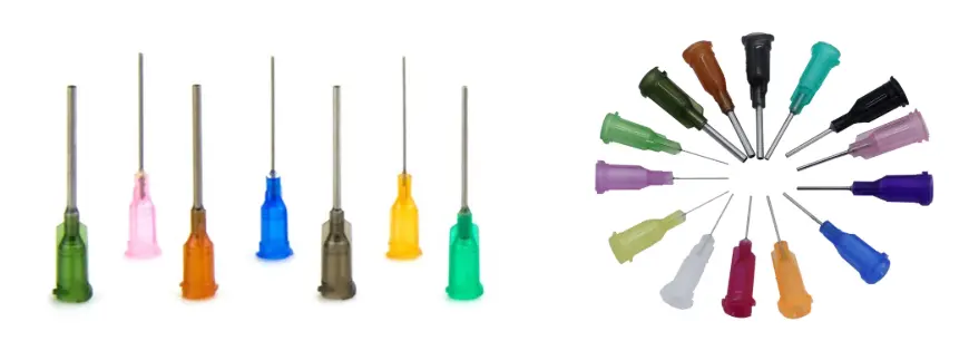
Most people seeing dispensing tips for the first time ask the same question: why are there so many versions? The short answer is that dispensing is not a single process.
It covers very different fluids, very different deposit requirements, and very different access conditions. A tip that works for a thin solvent on an open surface may be a poor fit for a filled adhesive inside a narrow, recessed area.
That is why no single tip geometry works well for every job. Each tip category exists to solve a different combination of fluid behavior, access constraints, and output requirements.
The Five Factors That Help Narrow the Right Tip Category
Before comparing detailed specifications, it helps to look at a few high-level factors that usually eliminate poor category matches early. These factors do not replace application testing or detailed selection work, but they provide a useful framework for understanding why one category may be considered earlier than another.
Fluid viscosity and behavior
Fluid behavior is usually the first thing to define. Viscosity is the obvious starting point, but it is not the only one. You also need to consider whether the fluid cures easily, reacts with metal, or becomes sensitive under UV exposure.
Required deposit shape
The target deposit also changes category relevance. Some processes need a narrow line or a controlled dot, while others need a wider ribbon or a more spread-out layer. At this stage, the goal is not to confirm a model, but to understand which general outlet behaviors are compatible with the result you need.
Access conditions
Physical access often narrows the category before size is even considered. If the dispense point is open, a simple geometry may be enough. If surrounding components, housings, walls, or recesses block the approach path, the category may need to change to match the physical route rather than the fluid alone.
Substrate sensitivity
If the tip may touch or move close to a sensitive surface — such as coated parts, soft plastics, or populated PCBs — tip hardness matters. A rigid tip that brushes a delicate area can leave scratches or damage components. In those cases, you need to think about both tip material and end geometry.
Chemical compatibility
Not every tip material works with every fluid. Some solvents can attack polypropylene, and some reactive adhesives may cure more easily inside a standard metal tip. UV-sensitive fluids may also be better handled with opaque or UV-blocking materials, depending on how much light exposure the process involves. Compatibility is one of the easiest checks to overlook, and one of the more frustrating problems to discover mid-process.
Common Tip Categories and When to Use Each
If you want a quick overview, the table below shows the most common dispensing tip categories, where they are generally used, and what usually drives that choice.
(The categories below are intended as a general reference, not as a substitute for detailed product comparison. Their purpose is to show how category differences are usually understood at a practical level before moving into detailed specification or application testing.)
| Tip Category | Common Process Context | Main Reason It Is Considered |
| Blunt tip (straight) | General-purpose: adhesives, lubricants, solvents | Open access, no specialized bead profile required |
| Tapered tip | Medium–high viscosity: epoxies, silicones, pastes | Clean bead cutoff needed on thick fluids |
| Angled tip (45° / 90°) | Confined spaces, obstructed approach paths | Physical access is the constraint |
| Flexible tip | Sensitive surfaces, curved or deep cavities | Rigid tip risks surface damage or cannot reach target |
| Brush tip | Spreading / coating low-viscosity fluids | Coverage area matters more than deposit precision |
| Oval / flat orifice tip | Wide ribbon bead: sealants, TIM, gap fillers | Bead width exceeds bead diameter, single-pass coverage needed |
| PTFE-lined tip | Reactive adhesives: cyanoacrylates, anaerobics | Fluid cures or reacts on contact with metal |
| Stainless steel tip | High-pressure, automated, solvent-heavy processes | Durability, temperature resistance, precise alignment |
| Precision nozzle (SS) | Micro-volume: underfill, encapsulants, optics | Micron-level accuracy required |
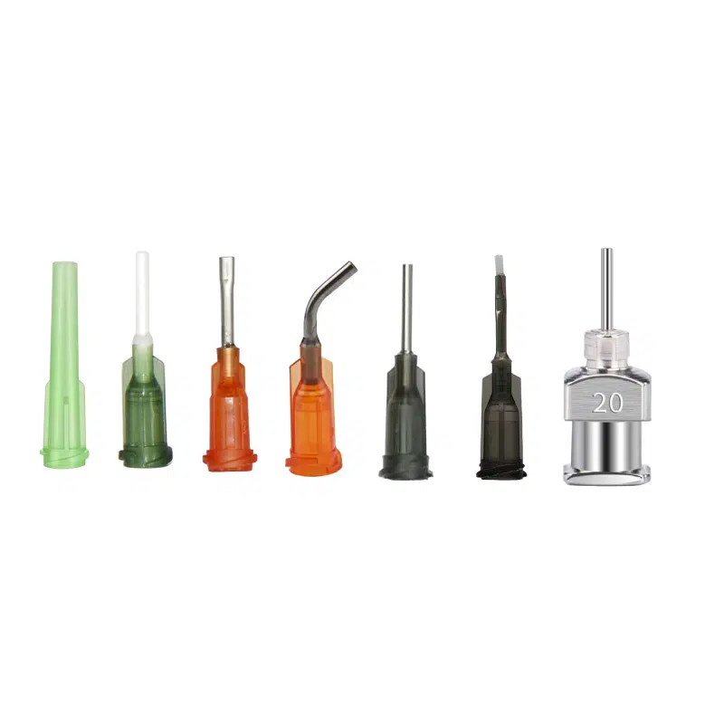
Blunt Tip (Straight, General-Purpose)
A straight blunt tip is usually the default starting point for general dispensing work. It fits many standard dispensing setups and works across a wide range of fluids.
It makes sense when access is open, the fluid is not reactive with the tip material, and you do not need a specialized bead shape. It becomes a weaker choice when the path is blocked, the fluid reacts at the tip, or the application needs a ribbon bead or broad coverage instead of a dot or line.
Tapered Tip
Tapered tips narrow gradually from the hub to the orifice. This geometry reduces backpressure buildup with medium- to high-viscosity fluids and produces a cleaner fluid cutoff — meaning less dripping and stringing after each dispense cycle ends.
Choose it when dispensing medium to high viscosity materials — epoxies, silicones, solder pastes — where clean cutoff matters. Avoid it for very low-viscosity fluids, where the tapered design adds no benefit and can increase drip tendency.
Angled Tip (45° and 90°)
The defining reason to use an angled tip is physical access: when the dispense point is blocked by surrounding parts, tall connectors, housings, or other obstructions that prevent a straight tip from reaching the target.
Use an angled tip when a straight approach is physically blocked. In many cases, 45° works for moderate access constraints, while 90° is more useful when the path is tighter or more sharply obstructed.
Flexible Tip
Flexible tips are usually made from soft polymers that can bend around obstacles or reach angles that a rigid tip cannot handle easily. Unlike angled tips with a fixed bend, they can often be repositioned between jobs without changing tooling.
They are useful when the dispense path curves, the substrate is sensitive, or the setup changes from job to job. Under higher backpressure, however, flexible tips can become less stable, so they are usually not the first choice for thicker materials.
Brush Tip
Brush tips replace the rigid orifice with fine bristles, transforming the dispensing action from a directed stream to a spreading motion. The goal here is even film coverage over an area, not controlled deposit placement.
Choose it when the goal is consistent surface coverage — applying flux, lubricant, activator, or thin adhesive across a broad area. Avoid it when dispensing medium or high viscosity fluids, or when positional accuracy is required. Brush tips do not produce controlled dots or lines.
Oval / Flat Orifice Tip
Oval or flat-orifice tips use an elongated opening instead of a round bore, which helps produce a ribbon-style bead. They are useful when the application needs wider, single-pass coverage that a standard round tip would struggle to achieve efficiently.
They are commonly considered for seam sealing, gasketing, and other jobs where bead width matters more than bead height. They are less suitable when you need a round dot, a fine line, or tight positional control.
PTFE-Lined Tip
PTFE tips combine a metal outer structure with an internal PTFE lining. Because PTFE is chemically inert and non-wetting, this category is often considered when reactive adhesives cure too easily at the orifice or inside a standard metal tip.
If the fluid reacts with metal or repeatedly cures at the tip, PTFE-lined designs may be worth testing. If the fluid is already stable in a standard tip, the added complexity may not be necessary.
Stainless Steel Tip
Stainless steel tips are often chosen for their rigidity, temperature tolerance, and stable alignment in automated dispensing setups. They are also useful in processes where solvents may attack softer plastic materials.
They are commonly considered for automated work, higher-temperature conditions, or processes that need consistent alignment over longer runs. They are a weaker fit when the fluid reacts with metal or when the substrate cannot tolerate contact with a hard tip.
Stainless Steel Precision Nozzle
Precision nozzles are a specialized subcategory of stainless steel tips used in very small-volume dispensing applications. They are generally considered when deposit size control needs to be tighter than what a standard tip can provide.
They may be relevant for applications such as underfill, sensor encapsulation, or optical assembly. If the fluid contains larger particles or fillers, however, a very tight bore can become harder to keep stable.
Why Size Variables Matter After Category-Level Understanding
Choosing a tip category narrows the field significantly, but gauge, length, and internal diameter still shape how the tip behaves in the real process. These three variables interact, so it helps to understand that relationship before moving into detailed product selection.
How Gauge and ID Influence Flow Behavior
Higher gauge numbers usually mean a smaller tip size and, in many cases, a smaller internal diameter. A smaller ID increases flow resistance, which can help with finer deposits in low-viscosity fluids. A larger flow path is usually easier to manage with thicker or filled materials.
How Tip Length Affects Reach and Stability
Tip length is mainly a trade-off between reach and stability. Longer tips help you reach recessed or obstructed dispense points, but they are also more likely to deflect, especially in automated systems where tip-to-substrate height is tightly controlled. A longer fluid path can also add pressure drop.
How Gauge, Length, and Viscosity Interact
These variables do not act independently. Increasing tip length or reducing flow path size both raise pressure drop, and that becomes more noticeable as viscosity increases.
In most cases, it makes more sense to narrow the tip category first, then check gauge and length against the actual fluid and access requirements. If you need more detailed guidance on gauge and tip configuration, see our dispensing tip selection guide.
Frequently Asked Questions
Why are there so many dispensing tip types?
Because dispensing requirements change from one process to another. Fluid behavior, deposit goals, access limitations, compatibility issues, and substrate sensitivity do not stay constant across applications, so category differences exist to reflect those process differences.
What is the difference between a tip category and a tip size?
Category refers to the tip geometry and material type — blunt, tapered, angled, flexible, PTFE-lined, and so on. Size refers to gauge, length, and ID within that category. Category is the first decision; size is the refinement that follows once the right category is identified.
When should I move from a category overview to detailed selection work?
Once the tip category is identified, further refinement — gauge, length, material verification — requires testing with your actual fluid and dispenser. Viscosity references and application examples provide a starting point, but dispensing behavior depends on fluid lot, temperature, dispensing pressure, and cycle timing. The specifications in a selection guide are a reference frame, not a substitute for process validation.
Conclusion
Dispensing tips may look like small components, but they shape some of the most important parts of the dispensing process: how the fluid flows, how stable the bead remains, whether the target area can be reached cleanly, and whether the result stays consistent from run to run.
That is why understanding tip categories matters. Once you understand how geometry, material, gauge, length, and application conditions relate to one another, it becomes much easier to see why different dispensing jobs call for different tip types.
This guide is meant to give you that overall framework. If you want to explore the available tip formats in more detail, visit our Dispensing Tips product page.